I am into all types of synthesizers, old and new, and recently I’ve taken to the sound of older video game sound chips. I recently desoldered the NES’s 2A03 processor off its mainboard and have it in partial communication with an Arudino, but rewind, do I really know enough about composing music on that chip? Not yet. So there’s only one thing to do about that.
6502 Assembler
The NES was programmed in 6502 assembly language, and lucky for me, it actually has a really straight forward instruction set, but still, last month I was still not familiar with it enough to make anything. Now, usually when I don’t understand something, I write a program that somehow involves whatever topic I’m learning. You can’t write a program like an assembler without understanding how the processor for that assembler works, so I wrote my own assembler for the NES called n65.
This is the assembler I will be using in this article, and to help me compose music on the NES.
You can easily install n65 through RubyGems.org:
gem install n65
Programming Basics
Before we can get the NES to make any sounds, there are a few things to know about writing
programs for it. The 6502 is an 8-bit processor, because most of its internal work registers
are 8 bits wide. The general purpose registers you have direct control over are named
A, X, and Y. There are a few other 8 bit registers, such as the status register
and the stack pointer. The PC, or program counter though, is 16 bits wide, which means
the processor can address memory from $0000 to $ffff, a total of 65536 addressable bytes.
A NES does not have 64KB of actual RAM, the mainboard comes with 2KB of work RAM attached to the CPU, and 2KB of video RAM attached to the Picture Processing Unit, or PPU, which is actually a separate processor entirely, both of these processors run independantly of one another, but they can communicate through memory mapped registers.
The Audio Processing Unit, or APU, is also very much like a separate processor, although it is on the 2A03 chip, and is one of the things that makes a 2A03 different than other 6502s. You also communicate with the APU by writing values to memory mapped registers.
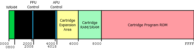
Image from www.jfbillingsley.com
Tiny, tiny amount of work RAM $800 bytes or 2KB. If you’ve never worked on anything
with such a small amount of RAM, well that’s actually the challenge here, that and having
no operating system is what makes it fun in my opinion :)
You don’t have to do everything yourself however, the PPU is a hardware tile and sprite engine, and the APU is a synthesizer. When the machine starts up, it is ready to display graphics and play sounds all by itself, all you need to do, and the majority of what your code is about, is moving the right data into the right places, and the hardware does the rest. This is typical of older generation consoles, and even newer ones up to at least the Nintendo DS.
Program Skeleton
Before we make our first beep, let’s set up a project skeleton that does the initialization that all NES games need to do. This involves setting the hardware into a known state, setting up the stack pointer, and clearing the work RAM.
When we produce a binary from our assembly code listing, we are writing code located
in the cartridge ROM area, shown above starting at $8000. The ROM binary we produce
would be written onto an actual ROM chip inside a NES cartridge, or more likely we’re
going to run this on an emulator, in which case n65 is setup to produce iNES formatted
“roms”.
The iNES file format is simply a 32 byte header, followed by at least one 16KB PROG ROM, and zero or more 8KB CHAR ROM sections. For now we can forget about CHAR ROM, let’s just create one PROG ROM section. These sections are either PROG for code or CHAR for graphics data, and are numbered in banks.
One last thing, the cartridge program ROM section is shown to be mapped from $8000 - $ffff,
this is 32KB total, not 16KB. If we specify 1 PROG ROM section in the header, that section
will be mirrored twice to cover that area of memory. This is important because we must
remember to write an interrupt vector table to $fffa. This is why we will assemble our
prog section bank 0 at $C000, because we are only using one bank of 16KB, it tends to
make more sense as far as addressing is concerned.
The interrupt vector is 3 16-bit addresses, that point to code for handling VBlank, Reset, and IRQ respectively. Every ROM must specify these, because the Reset vector points to the beginning of our code, think of it like specifying your main() function in a C program.
Ok here is an NES project skeleton that just initializes the hardware:
1 2 3 4 5 6 7 8 9 10 11 12 13 14 15 16 17 18 19 20 21 22 23 24 25 26 27 28 29 30 31 32 33 34 35 36 37 38 39 40 41 42 43 44 45 46 47 48 49 50 51 52 53 54 55 56 57 58 59 60 61 62 63 64 65 66 67 68 69 70 71 72 73 74 75 76 77 78 79 80 81 82 83 84 85 86 87 88 89 90 91 92 93 94 95 96 97 98 99 100 101 102 103 | |
So, let’s assemble this file using n65, and load it into an emulator. This means running n65 in your terminal.
1 2 3 4 5 6 7 8 9 10 | |
I develop on OSX, though n65 works under Linux, and probably Windows if you have Ruby installed.
If you named your assembly file program_skeleton.asm, by default you’re going to get a NES rom
file with the name program_skeleton.nes. The output filename can be changed to whatever you like
with the -o flag.
For an emulator, I am a fan of FCEUX because of its debugging and memory viewing capabilities, but the native version of FCEUX for OSX does not seem to include those features.
So, for debugging on OSX, I’ve taken to running FCEUX under Wine, which works well enough for that purpose. With FCEUX under Wine I can use the debugger, and if you run this ROM and open the memory hex editor you should see the first bit of RAM initialized like this:
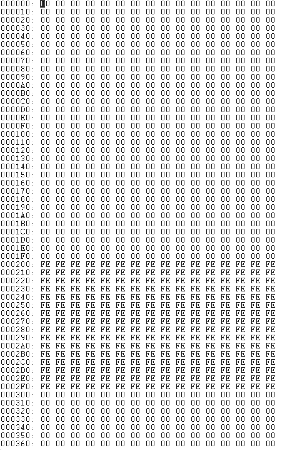
So, why did we initialize $200 - $2ff to $fe?
That 256 byte page of memory is typically used as “shadow OAM”. OAM is Object Attribute Memory, and resides in the PPU’s video RAM, but rather than update it directly, most people keep a copy of it here in CPU RAM, and transfer this copy to the PPU once per frame.
Remember how I said the NES has a hardware tile and sprite engine built into the PPU that just starts running on its own provided you put data in the right spots?
OAM has the x and y coordinates (among other attributes) of the 64 possible
hardware sprites on the NES, each sprite OAM is 4 bytes, and 64 * 4 = 256. Shoving $fe into
that area, will have moved all the sprites offscreen, because it is possible we’d see a bunch of
garbage sprites if we turned on the PPU and started coppying it over, so shadow OAM is typically
initialized with this value.
That’s enough about sprites and graphics though, since for now we are just interested in getting a simple sound out of the APU. In fact this program skeleton has turned off the PPU, and VBlank for now, and so rendering is totally disabled. We will turn it on again later when we want a stable timer for our music.
Next Step
The next easiest step to keep us moving forward, we can get the NES to make a beep using its APU. I’ve found a ton of good info on NESDev.
So here is a rundown of the parts of the APU:
$4000 - $4003Pulse 1$4004 - $4007Pulse 2$4008 - $400BTriangle$400C - $400FNoise$4010 - $4013DCM$4015Channel Enable
We’re going to want to use one of the Pulse oscillators to make a beep, so let’s use Pulse1.
We want to use the channel enable to enable that oscillator, then write the correct values into
the area $4000 - $4003, to make a concert A 440hz note come out with the right duty cycle.
Here is what the four bytes that control Pulse 1 do, notice that many things are packed into one 8-bit byte. Here is what each bit does:
nes.apu.pulse1.control
$4000 DDLC VVVV
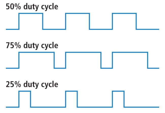
D : Duty cycle of the pulse wave 00 = 12.5% 01 = 25% 10 = 50% 11 = 75%
L : Length Counter Halt
C : Constant Volume
V : 4-bit volume
nes.apu.pulse1.ramp_control
$4001 EPPP NSSS
E : Enabled flag
P : Sweep Divider Period
N : Negate flag, inverts the sweep envelope
S : Shift count
nes.apu.pulse1.ft
$4002 TTTT TTTT
T : Low 8 bits of the timer that controls the frequency
nes.apu.pulse1.ct
$4003 LLLL LTTT
L : Length counter, if Length Counter Halt is 0, timer for note length
T : High 3 bits of timer that controls frequency
APU register $4001 does pitch sweeps, so let’s ignore that for now, and set up enough registers
to get a beep at our desired frequency of 440hz. I’ve listed symbolic names for each of the
registers as well, you get these symbolic names by the assembler directive .inc <nes.sym> in
the above code listing.
A pulse wave is a type of function generator that is either on or off, and the duty cycle parameter tells the APU what percentage of the time the wave is on or high.
Setting nes.apu.pulse1.control
Setting this effects the timbre of the sound, let’s just set it to 50% for now, this is a 2-bit
parameter and that corresponds to %10 in binary. The percentage sign prefix on a number means
binary, whereas the dollar sign means hexcidecimal, if you were wondering.
For volume, parameter V, we are allowed 4-bits of resolution, let’s play it as loud as possible,
%1111. We should also set bit C to %1, to allow constant volume throughout the whole time the note is
played, and set L to %0, because, we want to use the Length Counter, not halt it.
In the end, when we put all these parameters together into nes.apu.pulse1.control register, we
get the final value of %10011111, or $9f in hex. I find it a lot clearer to write out registers
with composite values in binary rather than hexcidecimal though.
Setting nes.apu.pulse1.ft
This register is for setting the frequency of the generated sound. An oscillator generates a waveform that resets itself periodically, and repeats a certain number of times per second. We want the pulse wave to reset at 440 times per second so we will get the note concert A, below middle C.
Internal to the APU is a counter which counts at a specific rate, related to the speed of the 2A03
processor, when it reaches the value we set to T, it will reset the period of the waveform, giving
us the right frequency. But it turns out the size of a register, being 8-bit cannot count high enough
to give us the low notes we expect to be able to produce in music.
Frequency in hertz has an inverse relationship to time in seconds:
That means the lower the note in hertz, the longer the timer will have to count, and means the counter
has to be at least 11-bits, so the value T spans all of the 8 bits in nes.apu.pulse1.ft and the
three extra high bits end up in nes.apu.pulse1.ct
There is a formula for determining this 11-bit counter number T from frequency in hertz:
Where CPU = 1789773.0, which is the speed of an NTSC Nintendo’s processor in hertz. This value
is different on a PAL NES, in that case CPU = 1662607.0.
Here is a Ruby function for determining the value of T:
1 2 3 4 5 6 7 8 9 10 11 12 13 14 | |
Hey, lucky us, the value 253 actually does fit within 8-bits. But that’s cutting it pretty close,
very much lower in frequency that number would have been higher than 255, and we would have needed
to put extra bits into nes.apu.pulse1.ct.
This gives me an idea, let’s allow both frequencies to be played. Let’s create a NES ROM that plays
a 220hz note if the B button is pushed, and a 440hz note if the A button is pushed.
So the 11-bit value of T for each frequency is then:
440hz = %000 11111101220hz = %001 11111011
Setting nes.apu.pulse1.ct
Like we just mentioned, nes.apu.pulse1.ct contains 5 bits of length counter, to control the duration
of our note, and the 3 high bits from T the frequency counter.
For now let’s set the note length counter to its highest value, %11111
Reading from the Controller
Since we just decided to allow button B to make one note, and button A to make another, we need to learn how to read the NES’s controller buttons. The best way to do this, is to create a subroutine which reads each of the buttons we care about, and stores their states into the work RAM area. This way, we can detect when the button is first pressed, and not just held down.
Controller 1, like everything else, is a memory mapped device, and it is mapped to address $4016,
or, if we’re using my symbolic names, simply nes.controller1.
To tell the controller we want to read its button states, we have to “strobe” the controller, which
just means to write a $01 and then a $00 to it in succession. Then bit 0 of the next eight bytes
that we read out of that location reveal the state of each button in the following order:
- A
- B
- Select
- Start
- Up
- Down
- Left
- Right
Putting it all together
Here are some modifications and additions. First we add an initialize subroutine to our reset which enables both pulse1 and pulse2, and turns the PPU back on so that we get VBlank interrupts again.
The VBlank is the portion of time when the screen is in-between drawing, and is a handy place you
can put code you would like run every frame, at 60 frames per second. We use this to call our
read_input subroutine repeatedly.
The read_input subroutine strobes controller1 and reads the state of the A and B buttons,
and stores their state into controller_state as defined in RAM at address $0000 in the zero
page. The zero page is the first 256 bytes of RAM, which can be quickly accessed using only
an 8-bit address, when you see a zp suffix on an instruction, you are telling the assembler
it can use the quick zero page addressing mode.
We store the state of the A and B buttons in RAM so that we can tell when they are first
changing state, so that we only play our notes once per button press.
Then we’ve added two subroutines which load the values discussed above into the APU to get
our notes to play. nes.apu.pulse1 and nes.apu.pulse2 both operate in the exact same way,
which is why we turned them both on, each button triggers one of the two pulse generators,
which means we can hear both sounds at once, overlapping if needed.
1 2 3 4 5 6 7 8 9 10 11 12 13 14 15 16 17 18 19 20 21 22 23 24 25 26 27 28 29 30 31 32 33 34 35 36 37 38 39 40 41 42 43 44 45 46 47 48 49 50 51 52 53 54 55 56 57 58 59 60 61 62 63 64 65 66 67 68 69 70 71 72 73 74 75 76 77 78 79 80 81 82 83 84 85 86 87 88 89 90 91 92 93 94 95 96 97 98 99 100 101 102 103 104 105 106 107 108 109 110 111 112 113 114 115 116 117 | |
Conclusion
So that’s it for our first attempts to get the NES to make sounds. I have actually been working on MIDI to NES converter, which converts a MIDI file into a byte stream that can be quickly written to the APU registers at the correct tempo, which is almost complete. That will be the topic of my next post.
You can find n65, my NES assembler here.
And the source code for this NES sound example here